Work order
Open the fuel filler hatch.
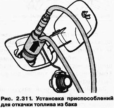
Insert suction hose (pic. 2.311) fuel pumping device VAS 5190 about 170-180 cm into the fuel tank neck and pump out the fuel.

NOTE: If fuel stops pumping, the fuel tank is empty enough that the sensor flange can be safely opened. With the remaining fuel, the tank can be removed.
If it is necessary to work on the fuel pumps and sensors, perform the following operations:
Cut the carpet from point A to point B at the pre-cut location (rice. 2.309).
Turn off nuts 1 fastenings of a cover. If necessary, unscrew the fastening of the armrest support 2 or the support bracket.
Place a rag on the connection for the fuel supply line and the auxiliary heater fuel line and disconnect the hose.
NOTE: To do this, press the button on the coupler.
Disconnect the plug of the fuel pump and fuel level sensor.
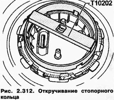
Unscrew the retaining ring using the T10202 key from the sensor flange (pic. 2.312).

Carefully lift up the sensor flange.
Insert the extraction hose of the VAS 5190 fuel extractor as far as possible into the right and left sides of the fuel tank and extract the fuel.
When working on the left side of the tank, follow the instructions above.
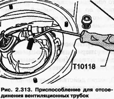
The buttons on the hose connectors may not be pressed when the ventilation tubes are disconnected. In this case, use the installation tool T10118 (pic. 2.313).

For further work on the internal parts of the fuel tank, the sensor flanges can remain removed.
If it was only necessary to drain the fuel from the tank, reinstall the sensor flanges.
Before installing, check the flange O-rings for tightness.
NOTE: If o-rings are swollen due to exposure to fuel, they should be replaced.
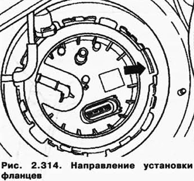
Mount the sensor flanges with the fixing plate in the direction of travel (pic. 2.314).

Tighten the retaining rings on the right and left using the key T10202 with a torque of 145 Nm.

Visitor comments