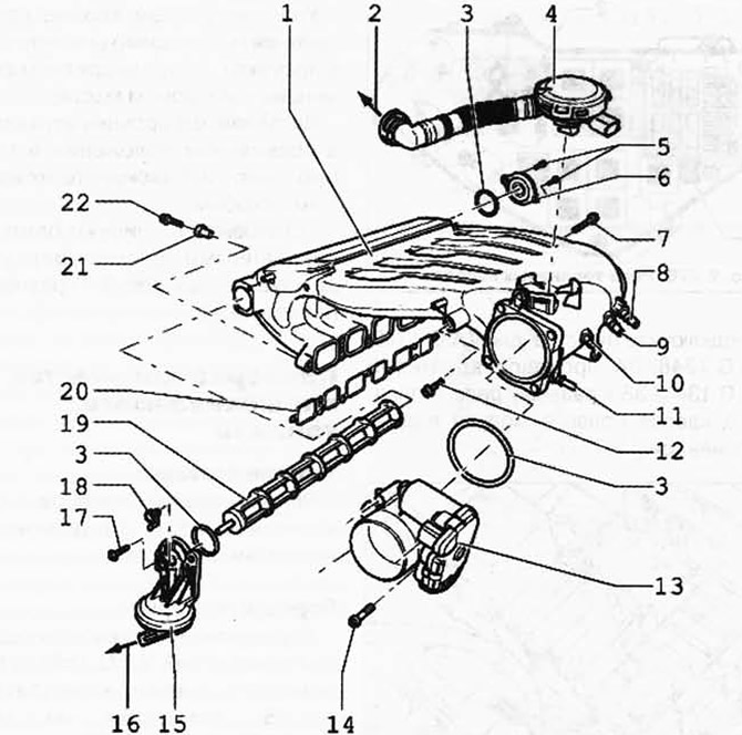
Pic. 2.271. Intake manifold details:
1 - intake manifold; 2 - to the cylinder head cover; 3 - sealing ring; 4 - crankcase ventilation valve; 5 - bolt 10 Nm; 6 - bearing cover; 7 - bolt 20 Nm; 8 - vacuum fitting; 9 - vacuum fitting (in vehicles with engine code AZZ, BKJ, BMV and BRJ is plugged); 10 - vacuum fitting; 11 - vacuum fitting; 12 - bolt 20 Nm; 13 - throttle control module J338; 14 - bolt 10 Nm; 15 - vacuum drive; 16 - to the valve for step change in the geometry of the inlet pipe N156; 17 - bolt 10 Nm; 18 - setting lever; 19 - contact cylinder; 20 - gasket; 21 - fitted sleeve; 22 - bolt 13 Nm.
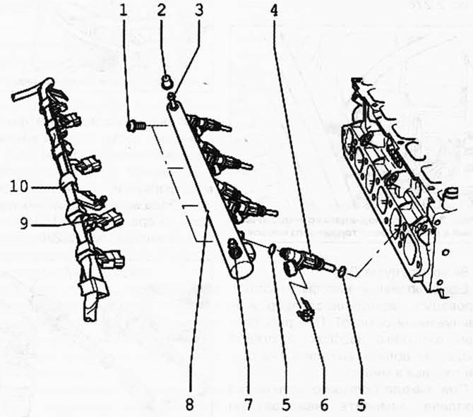
Pic. 2.272. Fuel Rail Details:
1 - bolt 10 Nm; 2 - protective cap; 3 - air valve; 4 - nozzle of cylinder 6 N84; 5 - sealing ring; 6 - mounting bracket; 7 - connecting fitting, fuel supply line; 8 - fuel rail; 9 - plug; 10 - wiring harness.
Technical characteristics of the injection system of gasoline engines
| Engine code | AZZ | BAA | BKJ | BMV | BMC | BRJ |
| Idling testing | ||||||
| Idling speed, min-1 | 650-750 | 650-750 | 650-750 | 650-750 | 650-750 | 650-750 |
| Engine control unit | Motronic ME7.1.1 | Motronic ME7.1.1 | Motronic ME7.1.1 | Motronic ME7.1.1 | Motronic METL.1 | Motronic ME7.1.1 |
| System designation | ||||||
| Speed limitation, min-1 | from about 6500 | from about 6500 | from about 6500 | from about 6500 | from about 6500 | from about 6500 |
The fuel supply hoses in the engine compartment may only be secured with spring clips. The use of clamping collars and clamps with threaded fastening is not allowed.
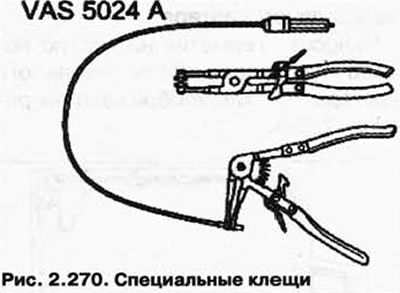
For the installation of spring clamps, we recommend using the spring clamp pliers VAS 5024 A or the pliers VAG 1921 (pic. 2.270).
A voltage of at least 11.5 V is required to keep the electrical components working flawlessly.
Do not use sealants containing silicone. Silicone residues sucked in by the engine do not burn through and damage the lambda probes.
Disconnection of the pipeline of the air suspension compressor
Disconnect the pipeline from the air filter (pic. 2.273) in the following way.
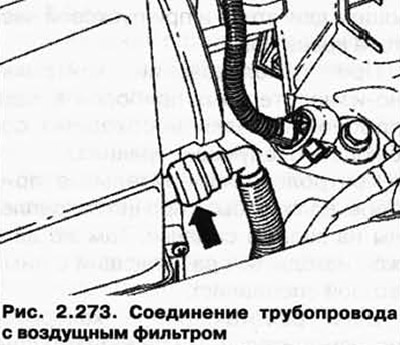
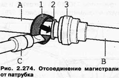
Carefully pry off the green retaining ring with 1 screwdriver. Then push the clamping ring 2 in the direction (pic. 2.273).
After that, disconnect the weakened line B from the nozzle A on the air filter (pic. 2.274).
Security measures
For safety reasons, before depressurizing the power system, fuses 13 and 14 should be removed from the fuse box, since the fuel pumps can be activated when the driver's door contact switch is activated.
Fuses 13 and 14 are located in the fuse box in the switch box, on the left side of the plenum box.
WARNING: The fuel line is under pressure. Before depressurizing the fuel system, connect the evacuation tool VAS 5226 and release the pressure.
To avoid personal injury and/or damage to the injection and ignition system, the following must be observed.
Disconnection and connection of electrical cables of the injection and ignition system, as well as measuring instruments, is only allowed when the ignition is switched off.
Do not touch or disconnect high voltage wires while the engine is running and at starting speed.
When using test instruments during a test drive, the following rules must be observed.
Gauges must be firmly attached to the rear seat. There should also be a second specialist working with them.
If a person working with instrumentation is in the front passenger seat, he or she may be injured when the airbag deploys.
If the engine is supposed to be rotated at the starting speed without starting it, disconnect the plugs from the ignition coils 1.6.
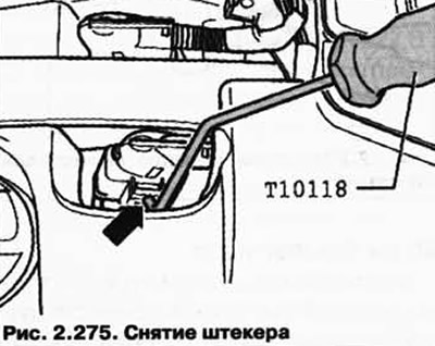
To do this, pry the T10118 mounting tool on the retainer and carefully remove the plug (pic. 2.275).

Visitor comments