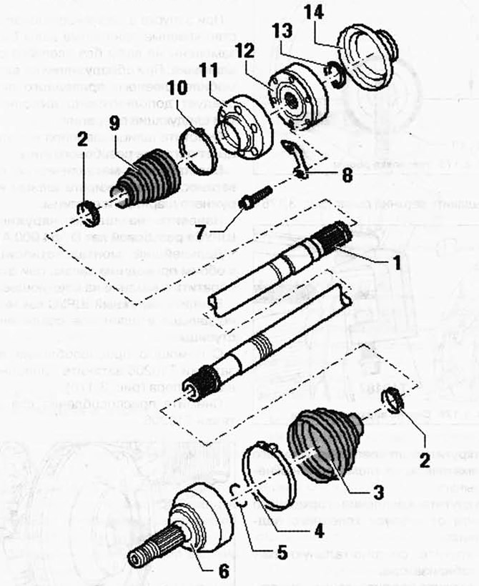
Pic. 3.173. Drive shaft:
1 - drive shaft; 2 - clamp; 3 - hinge boot; 4 - clamp; 5 - retaining ring; 6 - outer CV joint; 7 - screw with an internal asterisk; 8 - backing plate; 9 - anther of the inner CV joint; 10 - collar; 11 - cover; 12 - CV joint internal; 13 - retaining ring; 14 - cover.
Removing
ATTENTION: Switchable stabilizers must be switched on before starting work. Otherwise, unintentional activation of the stabilizers may result in injury.
Loosen the hex nut before removing.
NOTE: Loosen and tighten the hex nut only when the vehicle is on wheels. Do not drive the vehicle if the hex nut is loose. This may damage the wheel bearing.
NOTE: If it is necessary to move the vehicle with the drive shaft removed, the outer joint must be installed and tightened to 150 Nm.
Remove the wheel and raise the car.
Unscrew the drive shaft from the main gear. To unscrew the bolts, use the nozzle T10099/1.
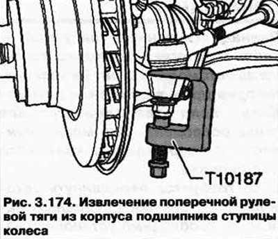
Press the tie rod out of the wheel bearing housing (pic. 3.174).
Press out the drive shaft.
At the same time, make sure that the hinges have sufficient freedom of movement.
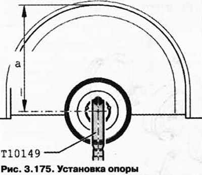
Rotate the wheel hub so that one of the wheel bolt holes is at the top.
Attach support T10149 with wheel bolt (pic. 3.175).
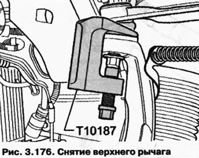
Pull out the top lever (pic. 3.176).
Unscrew the bolt securing the elastic pneumatic element to the lower arm.
Unbolt the brake hose from the wheel bearing housing.
Unscrew the connecting rod from the stabilizer.
Remove the bolt from the lower arm.
Lower the wheel bearing housing so that it is possible to remove the drive shaft.
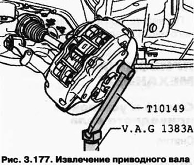
Remove the drive shaft (pic. 3.177).
Installation
ATTENTION: Switchable stabilizers must be switched on before starting work. Otherwise, unintentional activation of the stabilizers may result in injury.
At the start of mass production, the glued drive shafts were replaced by shafts without adhesive bonding. If a glued drive shaft is found on the vehicle, the following three operations must be additionally performed.
Clean the slots of the hinge and the hub from the remnants of thread varnish.
Restore the metal surface and degrease the outer joint and hub splines.
Apply thread varnish D 154 000 A1 to the splines of the outer CV joint.
The rest of the assembly applies to both drive shafts, while paying attention to the following.
Insert the outer CV joint as far as possible into the spline connection of the hub.
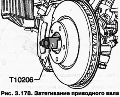
Using torque tool T10206, tighten the drive shaft until it stops (pic. 3.178).
Remove tightening tool T10206.
Further installation is carried out in the reverse order.
Tightening torques
Drive shaft to final drive flange M10 - 50 Nm + 90°;
Drive shaft to final drive flange M12 - 90 Nm + 90°;
Drive shaft to wheel bearing on vehicles with 16" wheels (use a new nut) - 200 Nm;
Drive shaft to wheel bearing on vehicles with 17"/18" wheels (use a new nut) - 500 Nm;
Upper arm to bearing housing (use a new nut) - 95 Nm.

Visitor comments