Dismantling
Loosen the wheel bolts, put the car on the goats.
Remove wheel.
Unscrew the stabilizer from the traction brace, for chassis numbers from 24 FN 019 683 - from the lower steering knuckle.
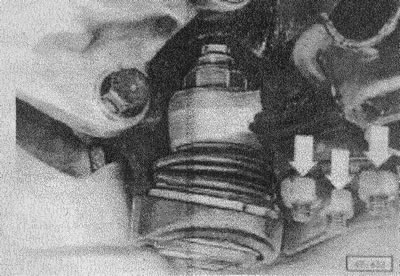
(40-633) for chassis numbers from 24 FH 019 682: unscrew the connection of the tie rod, steering knuckle and lower guide rod, shown by arrows.
From chassis number 24 FH 019 683: Unscrew the tie rod from the structure, then after loosening the lock nut, unscrew it from the guide rod.
Attention! The length of the traction strut determines the longitudinal inclination of the kingpin. Therefore, before loosening the nut, measure the length of the thread up to it and tighten it to its previous position during installation.
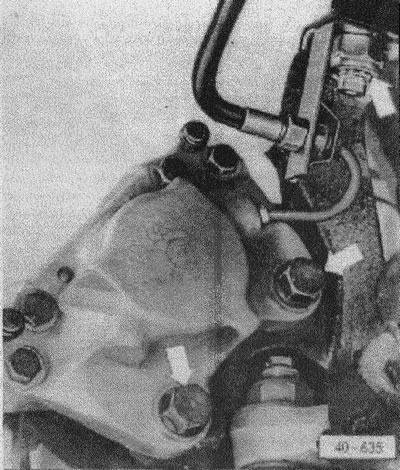
(40-635) unscrew the brake pad and brake hose holder (arrows).
Attention! Do not unscrew the brake hose!
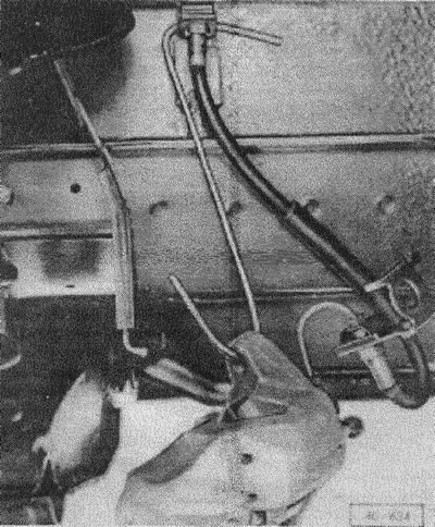
(40-634) hang the brake pad on the hook for the structure.
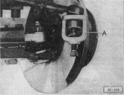
(40-646) remove the cotter pin of the tie rod nut, unscrew it and press the tie rods with a special puller.
Unscrew the upper hinge from the guide rod.
Separate the steering knuckle from the guide rod.
Release the shock absorber from the guide rod at the bottom.
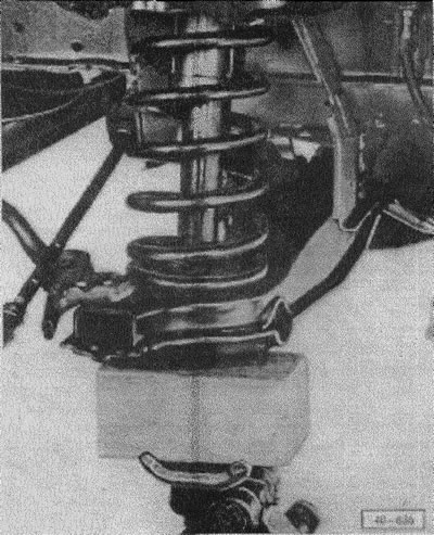
(40-636) Support the lower guide rod with a jack and remove the shock absorber bolt from the guide rod.
Gradually lower the jack and remove the helical spring, if necessary, unscrew the guide rod from the structure.
Installation
Fasten the guide rod with a torque of 90 Nm.
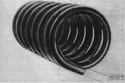
(40-379) determine the position of the spring. The straight end of the spring should be at the bottom.
Tape the backing to the top of the spring.
Insert coil spring (lower part of the spring into the recess in the guide rod).
Raise the guide rod with a jack and screw the shock absorber to the rod with a torque of 150 Nm.
Attach the steering knuckle to the guide rods. Screw* also the traction strut to the lower connection.
Attention! Each fixing bolt must always be bolted on with washer 12 230.5 or 12 230.6 and a new self-locking nut. Tighten the bolts to 65 Nm and retighten to 70 Nm.
From chassis number 24 FH 019 683: Screw the tie rod to the guide rod with a torque of 180 Nm. Screw on locknut. Screw the traction brace to the structure with a torque of 100 Nm. After this, it is recommended to adjust the pitch of the kingpin as soon as possible, see fig. "Vehicle measurement".
Screw the stabilizer and tighten with a torque of 30 Nm.
Insert tie rod, tighten nut to 30 Nm. If the cotter pin does not insert after this, tighten the nut further until the cotter pin enters.
Attach the brake cushion, tighten the cone bolt at the top, the hexagon bolt at the bottom with a torque of 160 Nm.
Screw on the wheel, lower the vehicle, cross-tighten the wheel bolts with a torque of 180 Nm.

Visitor comments