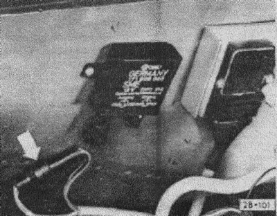
Disconnect the connectors of the idle speed stabilization system switching unit and connect them together, see Figure 28-101.

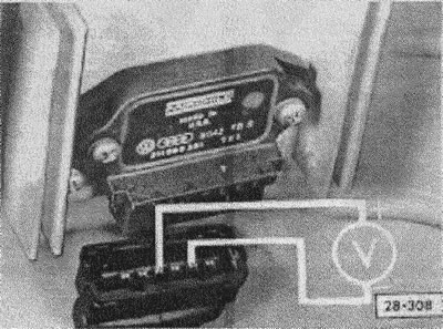
Disconnect the TSZ-M ignition switch connector.
Use a voltmeter to measure the voltage between pins 4 and 2 of the connector.

Turn on the ignition.
Set value: approximately battery voltage (12 in), otherwise determine from the electrical diagram and repair the open circuit.
Switch off the ignition.
Connect the TSZ-H ignition switch unit connector.
Disconnect Hall sensor connector (distributor).

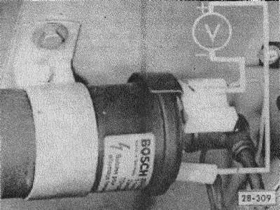
Connect a voltmeter to terminal 1 (-) and terminal 15 (+) ignition coils.
Turn on the ignition. Set value: not less than 12 volts. The voltage should drop to zero within 1-2 seconds. Otherwise, replace the TSZ-H unit and the ignition coil.
Touch the ground with the middle wire of the connector on the ignition distributor. The displayed value should briefly jump up to about 2 volts. Otherwise, find and eliminate the break in the middle wire or replace the switching unit.

Switch off the ignition.
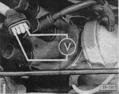
Connect a voltmeter to the outer pins of the Hall sensor connector (distributor).
Turn on the ignition. Set value: not less than 5 volts. Otherwise, determine and repair the open circuit between the Hall sensor connectors and the switching unit.
Connect the connectors to the DLS unit.

Visitor comments