Depending on the year of manufacture and the composition of the equipment, electrical wires and hoses are laid differently. Since it is impossible to touch each individual option, it is recommended to mark each wire with adhesive tape before removing the wires.
Electrical connectors usually have metal clips. Before disconnecting the connectors, release or press the clips on the side bracket.
Removing
Disconnect the ground lead from the battery.
Remove air filter.
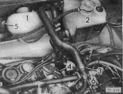
Open the cap of the expansion tank of the cooling system and drain the coolant.
Screw in and tighten the drain plug immediately with a new gasket.
After disconnecting the water hoses -3- and -4-, loosen the bolts -5- and remove the filling tank 1-1 and the expansion tank -2-.
Detach hose -6- from water pipe.
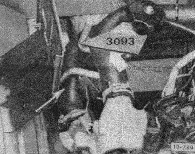
Seal water hoses with hose clamps (VW-No. 3093 or wire -arrows- - and disconnect from the water pump.
Seal water hoses with hose clamps (VW-No. 3094 or wire and disconnect.
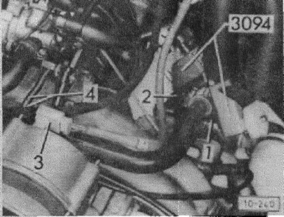
Disconnect connector -3- from alternator.
Disconnect the throttle cable from the carburetor throttle or fuel injection device.
With automatic transmission: Remove lock and spring -4- from throttle control rod.
Vehicles with power steering
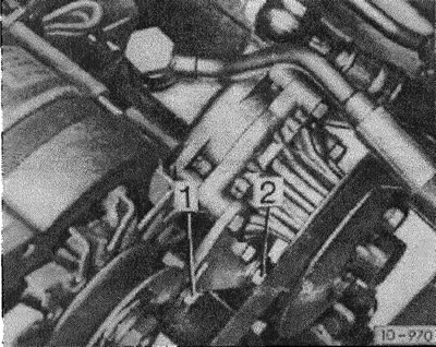
Remove bolts -1- and -2- from hydraulic pump bracket and remove V-belt. Lay the hydraulic pump with hoses connected to one side or hang it on a wire to the body. The bracket remains screwed into the motor block.
Attention: If hydraulic hoses open, air must be bled from the system after installation.
-Cars with air conditioning
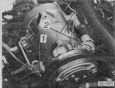
Remove bolts -1- and -2-. Remove the V-belt and hang the A/C compressor with hoses connected to the body.
Caution: The coolant circuit must not be opened. The tube is very sensitive to kinks, move the condenser carefully.
Carbureted engine
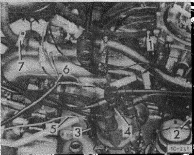
Disconnect fuel hoses -1- and -2-. Disconnect connectors -3- and -4- from ignition distributor.
Detach ground wire -5- from ground connection on crankcase.
Disconnect wiring harness -6- from connector.
Detach hose -7- from hydraulic brake booster.
Engine with fuel injection device
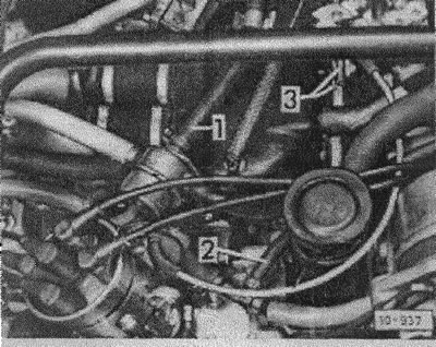
Disconnect and close petrol hoses -1- and -2-.
Disconnect the brake booster pipe.
Disconnect water hoses -2-, -3- and -4-.
Remove expansion tank -5- together with bracket.
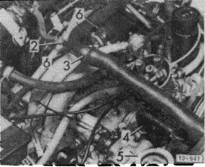
Disconnect the connectors of the following components of the fuel injection device: injectors, throttle switch, idle control, ignition distributor, hydraulic oil switches (brown and blue), intake manifold air temperature sensor, coolant temperature sensor, low coolant level indicator switch, fuel injection devices.
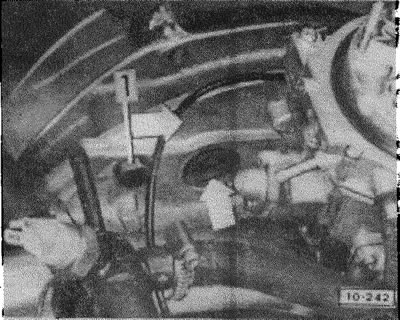
Loosen the bolt/nut -1- of the upper engine mounting.
With automatic transmission: through the mounting hole -arrow-, disconnect the driven disk from the converter in the engine crankcase by unscrewing the 3 M8 bolts.
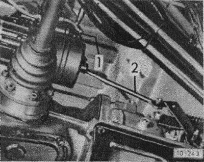
Unscrew wire -1- from starter.
With automatic transmission: Remove throttle control rod -2-.
By bus with all-wheel drive (Syncro)
Remove engine cover from below.
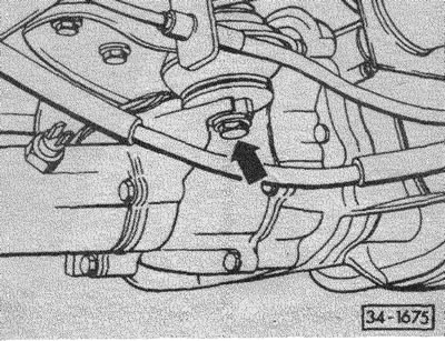
Loosen the gearbox front mounting bolts 3 turns.
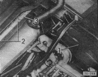
Unscrew covers -1- on left and right.
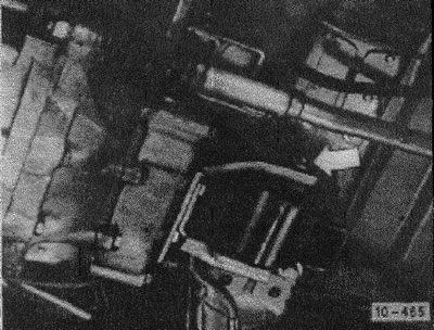
Unscrew securing bolt for gearbox mounting -arrow-.
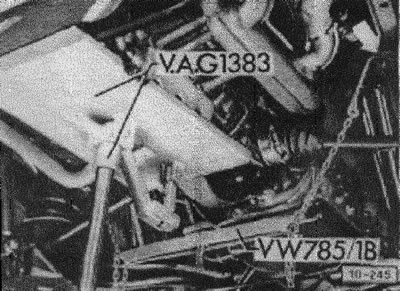
Install the engine lifting device VW 785\1B so that the distance between the gripper and the gearbox housing is about 120 mm. If no lifting device is available, substitute a garage jack with a wide shim.
Support the engine on a garage jack.
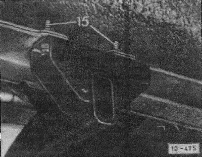
Loosen engine support bolts -15-.
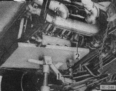
Lower the engine and gearbox so that the gearbox rests on the VW 785\1B engine jacks. When lowering, set the angle of inclination with the adjusting screw -1-. If there is no lifting device, the gearbox must be supported with a suitable jack.
Loosen nuts -2- of lower engine mounting bolts. Pull the engine off the gearbox housing. Slowly lower the garage jack and pull the engine down.
Installation
Before installation, the following work should be carried out: Thoroughly clean the surfaces of the engine and gearbox. Do not wash the clutch release bearing with clean gasoline or other detergents.
Bus with all-wheel drive: Clean the contact surfaces on the engine and gearbox and coat the contact surface on the engine with silicone sealant VAG No "AMV 17600505".
Check the clutch release bearing for wear and replace if necessary. Lightly grease the plastic ring with molybdenum sulfide grease.
Lightly coat the starter shaft bushing with multipurpose grease.
Lubricate the splines of the gearbox drive shaft with 100-molybdenum grease. Check clutch disc alignment.
Engage 1st gear so that the drive does not rotate.
Place the engine on a mobile garage jack. You can also install the engine on a fairly thick board 50 cm wide. In this case, in any case, 2 assistants are required.
Have an assistant lift the engine and at the same time introduce it into the engine compartment from above. Enter the engine very carefully so as not to damage the clutch disc, release bearing and drive shaft.
When installing the engine, simultaneously turn the belt pulley in both directions so that the crankshaft rotates and it is easier to insert into the clutch disc into the splined part of the drive shaft.
Firmly press the engine to the gearbox, and first insert the upper engine bolts and tighten them to a torque of 30 Nm, and then the lower ones.
Raise the engine with gearbox, install the engine beam bolts. Attention: Be sure to replace the self-locking nuts of the engine beam.
Take new self-locking engine mounting nuts, tighten the engine beam mounting bolts to the body to a torque of 25 Nm.
Tighten gearbox mounting to 30 Nm.
Screw on the engine covers.
Screw on the starter wire.
If equipped with automatic transmission: Install the throttle control rod.
Screw in and tighten to 20 Nm 3 transducer bolts through the mounting hole. Install the throttle link retainer and spring.
Connect the brake booster hose.
Push on earth wire -5- at earth connection point.
Fit connectors -3- and -4- of ignition distributor.
Connect and secure fuel hoses -1- and -2- with clamps.
Connect the throttle cable to the carburetor.
Install the top-up and expansion tanks.
Connect and clamp the water hoses to the tanks, water pump, water tube and engine.
Connect the generator connector.
Check that the drain plugs on the cylinder heads are closed, if necessary.
Engine with fuel injection device: Connect the fuel injection connector.
Carburetor engine: Connect wiring harness -6-.
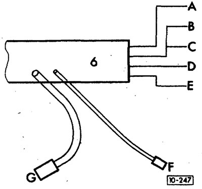
A - blue\black to brown oil circuit breaker with hydraulic drive.
B - red to red intake manifold heater.
C - 57 kW engine: black (from red) to black automatic engine start.
D - black on the temperature switch, to the air circulation shut-off valve and with: 40\44 kWh engine automatic engine start, 57 kWh engine partial load channel heater.
E - purple \ black for a temperature switch.
F - yellow / red on the coolant temperature sensor to the water pump.
G - connector for the low coolant level indicator switch.
Bus with all-wheel drive: Screw the lower engine cover and the front gearbox mounting to the bottom.
Fill with coolant.
Install an air filter.
Check engine oil level.
Connect ground wire to battery.
Start the engine.
Adjust idle speed.
Check ignition timing.
When the operating temperature is reached, check the coolant level and top up if necessary.
After a test drive, check for coolant leaks and, if necessary, tighten the hose clamps.

Visitor comments