Gasoline engine exhaust system

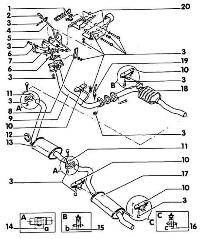
1. Bracket; 2. Cork; 3. Bolts (M6 - 10 Nm, M8 - 25 Nm, M10 - 40 Nm); 4. CO measurement tube; 5. Connection, 30 Nm; 6. Gasket; 7. Exhaust manifold; 8. Bracket - between intake manifold and exhaust manifold; 9. Front exhaust pipe; 10. Attachment; 11. Clamping clamp - align the exhaust system in the clamping sleeve in such a way in the longitudinal direction that the dimensions 14, 15 and 16 are maintained; 12. Retaining ring - pay attention to design; 13. Middle muffler; 14. Size "A" = 45–55 mm; 15. Size "b" = 1–2 mm; 16. Size "With" = 25–35 mm; 17. Exhaust muffler; 18. Catalyst; 19. Lambda probe, 50 Nm - Lubricate only the threads with G5 grease. G5 must not fall into the slotted area of the probe body; 20. Heat shield
For a gasoline engine, the exhaust system consists of the following parts: exhaust manifold, front exhaust pipe, catalytic converter, middle silencer and exhaust silencer. The diesel engine has, in addition to the exhaust manifold and front exhaust pipe, an additional silencer and a middle silencer. Required for adjusting the catalyst lambda probe (only petrol engine) screwed into the front tube near the connecting flange. The figures show the exhaust systems of 4-cylinder engines. They are fully compatible with 5-cylinder engine systems.
Diesel exhaust system

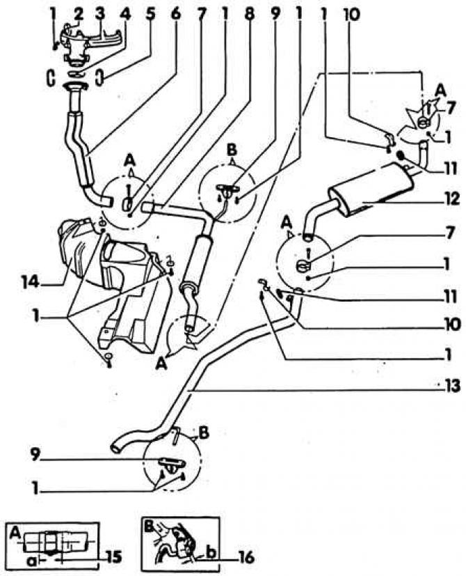
1. Nuts (M6 = 5 Nm, M8 = 25 Nm, M10 = 40 Nm); 2. Gasket; 3. Exhaust manifold; 4. Contact ring - replace only if damaged or leaking. Take out with a screwdriver; 5. Spring plate; 6. Front exhaust pipe; 7. Clamp clamp - Align the exhaust gas system in the clamp sleeves in the longitudinal direction so that dimensions 15 and 16 are maintained; 8. Additional muffler; 9. Suspension; 10. Holder; 11. Retaining ring; 12. Middle muffler; 13. Exhaust pipe; 14. Heat shield; 15. Size "A" = 50±5 mm; 16. Size "b" = 30±5
1.9 L turbocharged diesel engine (50 kW / 68 hp. With.) equipped with an additional catalytic converter between the front exhaust pipe and the additional muffler and exhaust gas return. Exhaust gas return is carried out through an exhaust manifold attached to the connecting pipe, which diverts part of the exhaust gases through a vacuum-controlled exhaust gas return valve to the intake manifold.
The regulation of the return flow of exhaust gases is carried out by a two-way valve, which, in turn, is controlled by the automatic heating control device.
With a cold engine (below 50°C) the return flow of exhaust gases is closed.
The steady motion power sensor on the injection pump determines that the exhaust gas should be fed back if the engine is running at uniform motion power (partial power).
From 1200 rpm, the return flow of exhaust gases is interrupted for 2 seconds, and from 2900 rpm it closes.
The corrective height sensor above sea level switches off the reverse flow at an altitude of approximately 100 m.
All components of the exhaust system are screwed together or connected by spring plates and can be replaced individually. Self-tightening nuts and gaskets are replaced after removal. Rubber shock absorbers are checked for porosity and damage, if necessary, replaced. The condition of the retaining rings is checked, damaged ones are replaced.
When installing a new exhaust system, it is recommended that all fasteners be replaced as well.

Visitor comments