Clutch

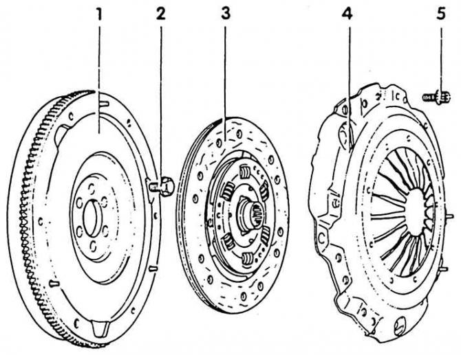
1. Flywheel - the friction surface of the friction linings should not be greasy, not oily, without scratches. Pay attention to the reliability of the fastening of the guide pins
2. Bolt - tightening torque: 6 Nm 1/4 turn (90°) puff. Always replace the bolts with new ones, lubricating the new screws with protective agents. Re-tightening can be done in several steps 3. Clutch disc - pay attention to the installation position, the spring cage points to the pressure plate
4. Pressure plate
5. Bolt, 20 Nm - tighten alternately, crosswise
Attention! The hub splines are nickel plated and no lubrication is required.
Clutch release mechanism

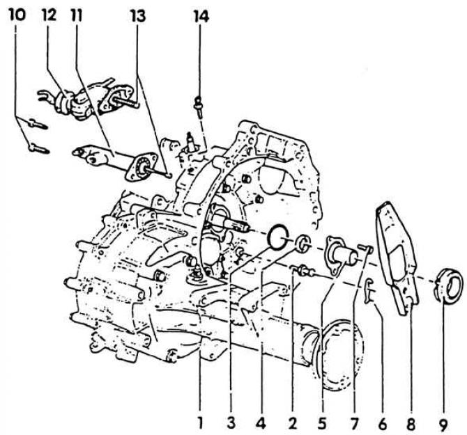
1. Gearbox; 2. Ball pin, 25 Nm - lubricate with MoS2 grease; 3. O-ring - always replace; 4. O-ring of the drive shaft - insert as far as it will go; 5. Guide sleeve - in the area of the engagement bearing, lubricate with MoS2 grease; 6. Locking plate - fasten to the clutch release lever; 7. Bolt, 15 Nm; 8. Clutch release lever; 9. Release bearing - do not wash the bearing, just wipe it. Replace noisy bearing. Lubricate the contact points with the release lever with MoS2 grease; 10. Bolt, 25 Nm; 11. Clutch slave cylinder; 12. Mechanical clutch drive; 13. Pusher - lubricate the end of the pusher with MoS2 grease; 14. Mounting pin - clutch release lock lever when assembling the gearbox. If the pin is not at hand, use the M8x22 screw. After assembling the gearbox, remove
Hydraulic clutch

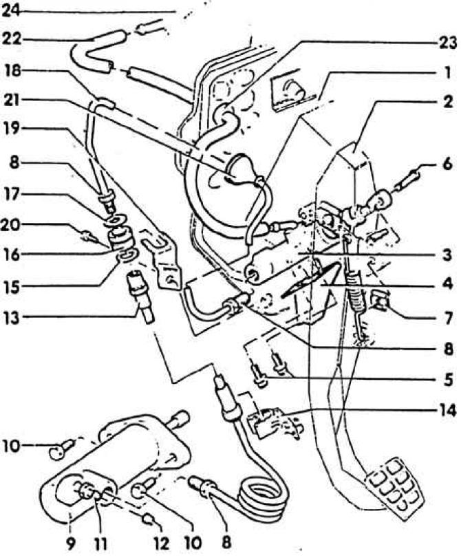
1. Connection plate with bearing bracket; 2. Clutch pedal; 3. Master cylinder; 4. Attaching the master cylinder to the bearing bracket; 5. Bolt, 20 Nm; 6. Support pin; 7. Stopper; 8. Hollow union nut, 20 Nm; 9. Working cylinder; 10. Bolts, 25 Nm; 11. Air release valve - bleed air from the hydraulic device, only with a device for bleeding air from the brake system. Working pressure max. - 2.5 bar; 12. Dust cap; 13. Pressure hose; 14. Hose bracket; 15. Washer - with a large internal diameter. Bulge towards the pressure pipeline; 16. Sleeve; 17. Washer - with a small internal diameter, a bulge towards the pressure pipeline; 18. Pressure pipeline; 19. Bracket - holds the pressure hose to the front wall; 20. Bolt; 21. Nozzle; 22. Hose; 23. Hose nozzle; 24. Brake fluid reservoir
Attention! Do not depress the clutch pedal after removing the cylinder.
Mechanical clutch drive

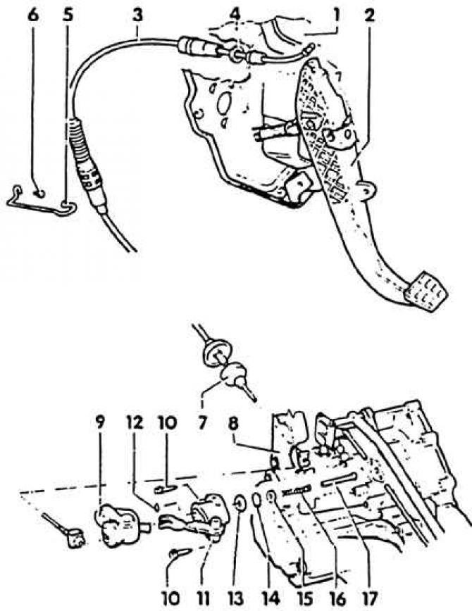
1. Connection plate with bearing bracket; 2. Clutch pedal; 3. Clutch cable with adjusting mechanism; 4. Gasket; 5. Support bracket; 6. A bolt of fastening of a lock bracket on a radiator; 7. Rubber shock absorber; 8. Stand support (gearboxes); 9. Sealing cuff; 10. Bolt, 25 Nm; 11. Drive housing with lever; 12. Safety washer - install approximately 8 mm from the end of the pusher; 13. Washer - always replace, must move freely; 14. Toothed ring - always replace. Drive through the puck with a suitable spike. Disconnect pusher first. When installing, hammer carefully. In this case, the convex side should point to the body. Pay attention to the fact that the washer 13 remains free; 15. Washer; 16. Spring; 17. Pusher - install after installing the toothed ring 14 and washer 13

Visitor comments